


Cover Spacing requirements for:
1.Efficiency of the bond between the concrete and the reinforcement [efficiency increases as cover increases].
2. Protection of reinforcement against corrosion.
3. Protection of the reinforcement from strength loss due to overheating in case of fire.
4. Extra cover in case abrasion and wear reduces cover depth over time.
Protection of the reinforcement from strength loss due to overheating in case of fire.
-normally specified in local building code
-typically ¾ in. cover to slab provides for 1-hr fire rating
-1 ½ in. cover to the stirrups of beam provides for 2-hr fire rating
Arrangement of bars must allow:
-Sufficient concrete on all sides of each bar to transfer forces into or out of the bars.
-Sufficient space so that the fresh concrete can be placed and compacted around all the bars.
-Sufficient space to allow vibrator to reach through to the bottom of a formed member. [pencil-type vibrators are typically 1½ in. to 2½ in. in diameter]
Minimum Bend Diameters
Most important for flexural members; applies to stirrups (based on feasibility of bending w/o breaking; or crushing concrete inside bend)
Visualize minimum bend diameter
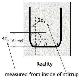
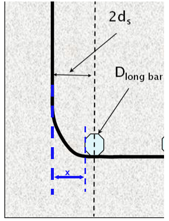
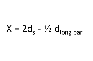
Minimum bend diameters for Stirrups No. 5 and smaller
Minimum bend diameters for Stirrups No. 6 and larger
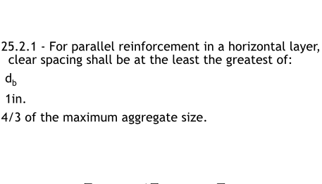
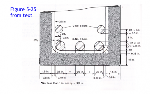
Spacing limit (clear spacing)
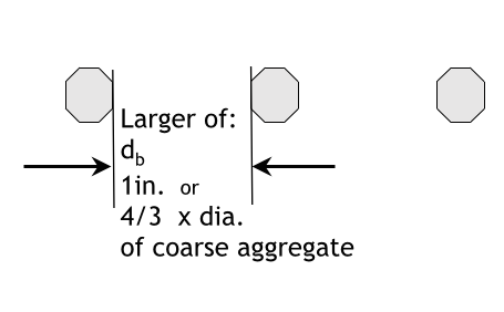
Spacing limit (clear spacing visual)
Spacing limit (two or more horizontal layers)
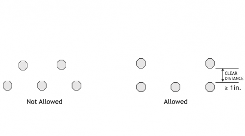
For parallel reinforcement placed in two or more horizontal layers, reinforcement in the upper layers shall be placed directly above reinforcement in the bottom layer with a clear spacing between layers of at least 1 in.
Spacing limit (two or more horizontal layers-allowed vs. not allowed)
Cover (aka Concrete Cover for Reinforcement)
Minimum cover for Concrete cast against and permanently in contact with ground
3in.
Minimum cover for Concrete exposed to weather or in contact with ground: No. 6 through No. 18 bars
2in.
Minimum cover for Concrete exposed to weather or in contact with ground: No. 5 bar, W31 or D31 wire, and smaller
1-1/2in.
Minimum cover for Concrete not exposed to weather or in contact with ground: Slabs, walls, joists: No. 14 and No. 18 bars
1-1/2in.
Minimum cover for Concrete not exposed to weather or in contact with ground: Slabs, walls, joists: No. 11 and smaller
3/4in.
Minimum cover for Concrete not exposed to weather or in contact with ground: Beams and columns: Primary reinforcement, ties, stirrups, spirals
1-1/2in.
Cover in Corrosive Environments
In corrosive environments or other severe exposure conditions, the specified concrete cover shall be increased as deemed necessary. The applicable requirements for concrete based on exposure categories in 19.3 shall be satisfied, or other protection shall be provided.
Cover in Fire Protection
Where the general building code (of which this code forms a part) requires a thickness of cover for fire protection greater than the concrete cover specified in 20.6.1, such greater thicknesses shall govern.
Checks for concrete cover include
1. Minimum bend diameters for stirrups
2. Minimum horizontal bar spacing
3. Minimum vertical bar spacing and bar placement
4. Minimum cover
5. Corrosive cover requirements, if applicable
6. Fire protection requirements, if applicable
Can a beam have too little reinforcement?
-As beam is loaded, initially concrete carries tension
-When beam cracks, tension is transferred to the reinforcing steel
-If the beam has too little steel, the steel could immediately yield
-This gives very little separation between the cracking load and the failure load
-This is viewed as BAD!
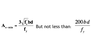
-So… ACI requires a minimum amount of flexural reinforcement
ACI Minimum Reinforcement Requirements
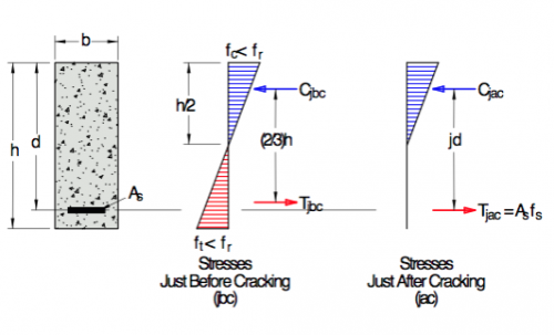
Objective in cover reinforcement
To ensure that just after cracking, tell has not yielded
On to beam design, what are we likely to know?
-Span
-Loads
-Possibly member dimensions (or limitations)
The Design Process
Knowns: b, h, f'c, fy, span lengths, loads
1. Compute: Mu (use appropriate factored loads!)
2. Compute Target Mn
3. Estimate d
4. Compute Required As - Two Methods
5. Select Bars
6. Check Steel Strain – determine ϕ factor (use actual d and As)
7. Check Min Steel: As ≥ As-min
8. Compute Actual Mn
9. Iterate as necessary
Compute Target Mn
Assume Tension Controlled ∴ φ =0.9
Recall Mn >= Mu/φ
Estimate d
Good ballpark starting point: h – (2.5 in. to 3.5 in.)
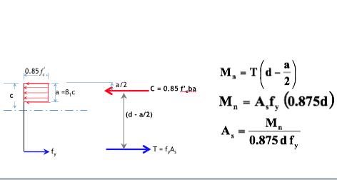
Compute Required As - Two Methods
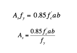
a. Easier, but greater chance of error (Assume Moment Arm = 0.875d)
b. Solve for a, then determine required As
Compute Required As - Easier, but greater chance of error
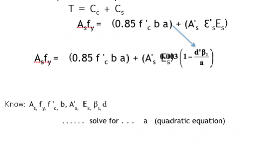
Compute Required As - Harder way (solve directly for a)
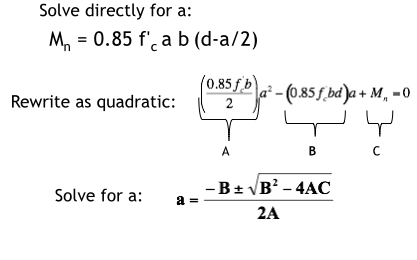
Compute Required As - Harder way (solve directly for a then determine required As)
Select Bars
-make sure everything fits
-pay attention to placement details
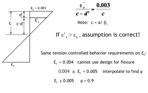
Check Steel Strain
-determine ϕ factor (use actual d and As)
-εt ≥ 0.005
Check min steel As>Asmin
Compute Actual Mn
check: ϕMn-act>Mu
First step beam design: b and h unknown
First step is to select trial dimensions using rule of thumb
Trial dimensions for height
l/16 <= h <= l/10 (l=length of beam)
or
l/10 <= h <= l/12
Trial dimensions for width
0.5d <= b <= 0.8d
or
h/2 <= b <= h/3
Trial dimensions for depth to centroid of steel
One row of tension steel
d = h - 2.5
Trial dimensions for depth to centroid of steel
Two rows of tension steel
d = h - 3.5
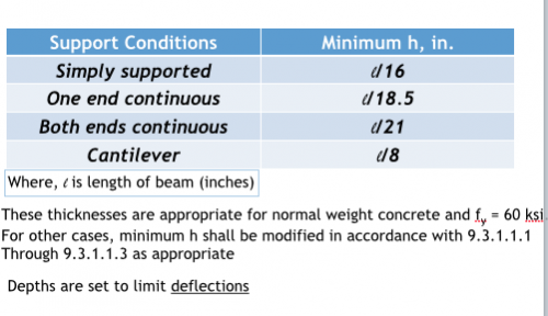
Minimum Depth of Non-prestressed Beams
Can Optimize dimensions for target Mn
-Avoid big beams with small amount of steel
-Avoid little beams with large amount of steel
-Ensure ductile behavior from the start
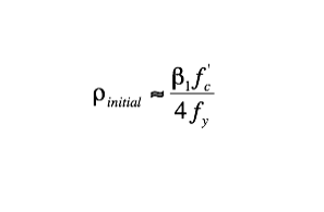
To derive steel reinforcement ratio
Start with target steel reinforcement ratio (p=As/bd)
Tension controlled behavior:
ϕ = 0.9
εt >= 0.005 (assume εt = 0.0075)
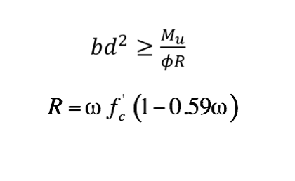
Use this relationship for design of singly reinforced rectangular cross-sections
b2^2 for design
The Design Process when b and h are unknown and cross section is optimized:
1. Assume dimensions and compute trial Mu
2. Select a reinforcing ratio that will ensure a ductile failure
3. Use formulas to optimize bd^2
-Select d and solve for b (or vice versa)
-Check minimum depth criteria per ACI Table 9.3.1.1
4. Compute new Mu and Required (target) Mn
5. Compute Required As (either of two methods)
6. Select Bars (check details)
7. Check Steel Strain and Determine ϕ (use actual d and As)
8. Check Minimum Steel
9. Compute Actual Mn and check ϕMn ≥ Mu
10. Iterate as necessary!
Why doubly reinforce?
1. Reduce long term deflections due to creep (compression steel retards creep)
2. Increased Ductility and Likelihood of Tension Controlled Failure (Good Behavior)
3. East of Fabrication (holds up the stirrups)
4. Limited beam depth
5. Locations which experience both positive and negative moments
Doubly reinforced Increases Ductility and Likelihood of Tension Controlled Failure (Good Behavior)
-Compression steel carries some of the compressive load, therefore less concrete is needed to carry remaining load.
-Thus, concrete stress block is not as deep
-Thus, NA moves higher in the cross-section
-Thus, more strain in tension steel
-Thus, more elongation in the steel
-Thus, more ductility in the cross-section
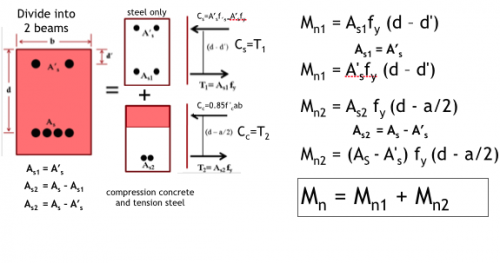
Stress and Force Diagram of Doubly Reinforced
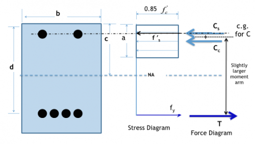
If all things are other wise equal....
....same b, d, As-tension, f'c, fy
The only gain is a slightly larger moment arm.
Moment capacity typically increase approximately 5%
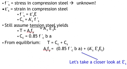
Analysis Approach Doubly Reinforced
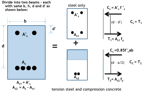
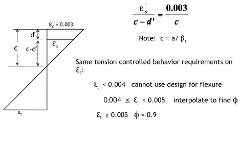
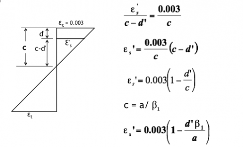
Strain Compatibility Doubly Reinforced
Analysis-Two Cases
Case I – Compression Steel Yields
Case II – Compression Steel Does Not Yield
Analysis Approach-Case 1
Strain Compatibility to Check Assumption-Case 1
Case II-Compression Steel Does Not Yield
Case II: Strain Diagram
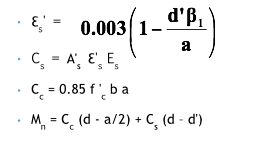
Case II: Equilibrium Equation
Case II: Once a is known, solve for
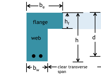
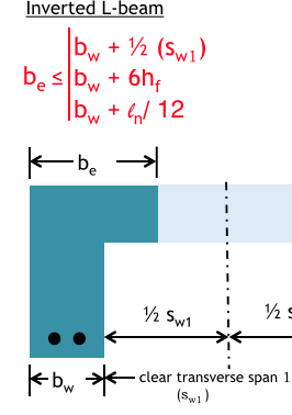
Dimensions for Inverted L-Beams
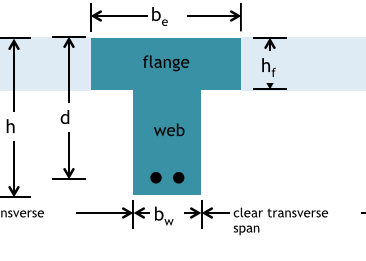
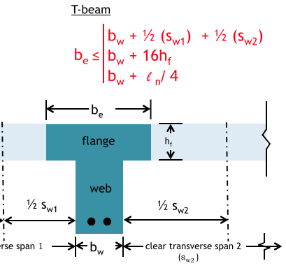
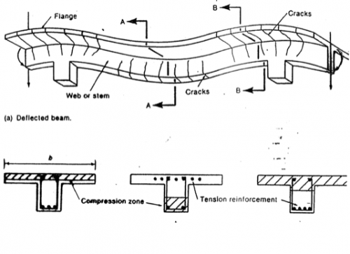
Dimensions for T-Beams
Transverse
perpendicular to beam span, l
ln=
clear span distance = face-of-support to face-of-support
Clear Transverse Span
Outside web of beam
to
Outside web of neighboring beam
Effective Flange Width Inverted L-Beam
Effective Flange Width T-Beam
Isolated T-Beam (not part of integral floor slab)
Two possible cases in T-Beams
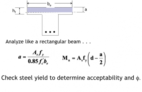
1. Compression zone in flange
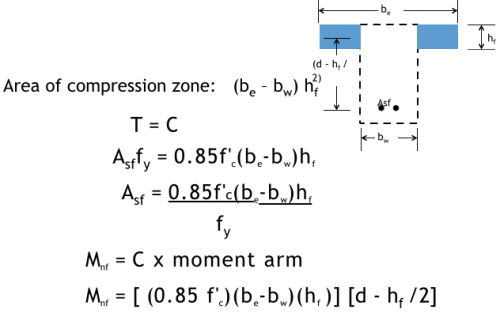
2. Compression zone extends into web
Compression zone in flange
Compression zone extends into web
Compression zone extends into web: Beam F
Compression zone extends into web: Beam W
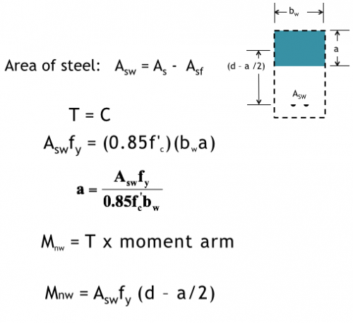
Total Moment Capacity & Checks
Mn = Mnf + Mnw
Check Steel Yield: same as before
Check As,min: same as before (using b = bw)
Special Case As-min: For statically determinant T-beams with flanges in tension
bw is replaced with the smaller of either 2 bw or the width of the flange. Most common case: simply-supported cantilever
Can use this approach for almost any oddball shape
Stresses with oddball shapes
Whitney Stress Block may not be exactly correct for these cases.
A Continuous T-Beam
other considerations with ratio p
-shallow beam-may need larger p
-concrete is cheap, steel more expensive
-space available